|
¡@ |
3. Energy Function |
¡@ |
|
¡@ |
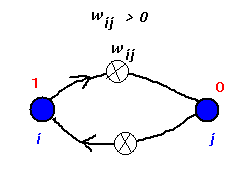
Defining an energy for the netThe dynamics of the net are described perfectly by the state transition table or diagram. However, greater insight may be derived if we can express this in terms of an energy function and, using this formulation, it is possible to show that stable states will always be reached in such a net. Consider two nodes two nodes in conflict
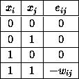
If j were given the chance to update or fire, the contribution to its activation from i is positive and this may well serve to bring j's activation above threshold and make it output a `1'. A similar situation would prevail if the initial output states of the two nodes had been reversed since the connection is symmetric. If, on the other hand, both units are `on' they are reinforcing each other's current output. The weight may therefore be thought of as fixing a constraint between i and j that tends to make them both take on the value `1'. A negative weight would tend to enforce opposite outputs. One way of viewing these networks is therefore as constraint satisfaction nets. This idea may be captured quantitatively in the form of a suitable energy function. Define ¡@
The values that ¡@
If the weight is positive then the last entry is negative and is
the lowest value in the table. If ¡@
This may be written ¡@ Since the sum includes each pair twice (as It is now instructive to see what the change in energy is when a node fires. Suppose node k is chosen to be updated. Write the energy E by singling out the terms involving this node. ¡@
Now, because ¡@
For ease of notation, denote the first sum by S and take
the ¡@
but the sum here is just the activation of the kth node so that ¡@ Let the energy after k has updated be ¡@ Denote the change in energy ¡@
There are now two cases to consider ¡@
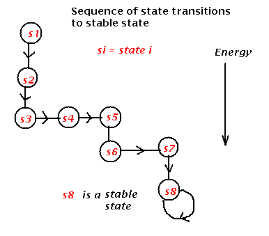
Thus, for any node being updated we always have state transitions to stable state
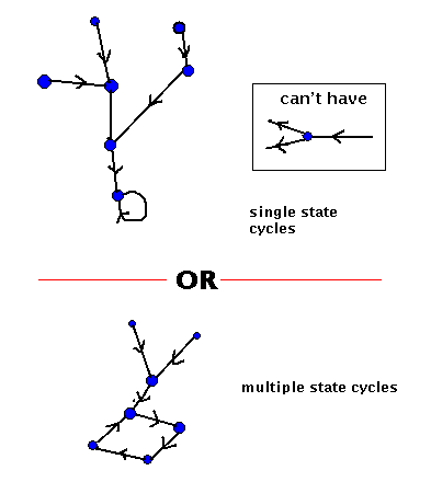
In the example given above, all state have zero energy except for state 5 which has energy 2, and the stable states 3 and 6 which have energy -1. Asynchronous vs. synchronous updateSo far we have allowed only a single node to update or fire at any time step. All nodes are possible candidates for update and so they operate asynchronously; that is, there is no coordination between them in time. The other extreme case occurs if we make all nodes fire at the same time, in which case we say there is synchronous update. To do this, we must ensure that each nodes previous output is available to the rest of the net until all nodes have evaluated their activation and been updated. It is therefore necessary to store both the current state vector and the next state vector. The behaviour is now deterministic; given any state, a state transition occurs to a well defined next state, there being no probabilistic behaviour. The analysis, in terms of energy changes at each update, given above no longer applies but there is now a simplified type of state diagram in which only a single arc emerges from any state. This allows us to predict, once again, the general type of behaviour. In particular, state-cycles occur again but now there is the possibility for multiple-state cycles. state diagrams for synchronous update
These may be useful in storing sequences of events or patterns. A little thought will show that the (single) state cycles remain the same under synchronous dynamics so the single stored patterns remain the same under both dynamics. Ways of inputting informationSo far it has been assumed that the net is started in some initial state (the memory cue) and the whole net allowed to run freely until a state cycle is encountered (recall slide of noisy `T'). There is another possibility in which some part of the net has its outputs fixed while the remainder is allowed to update. The part that is fixed is said to be clamped and if the clamp forms part of a state cycle, the remainder (unclamped) part of the net will complete the pattern stored at that cycle (recall slide of partially correct `T'). Which mode is used will depend on any prior knowledge about parts of the cue being uncorrupted or noise free. ¡@ ¡@ |
¡@ |
|
¡@ |
|
¡@ |


